Does it still work…?

Spurred on by the fact that there’s a leap second tonight, I thought I’d get the clock out and see if it still worked.

Initially it wasn’t looking great – the parity checks were failing…

….but after a bit of tweaking on the pots…..

Hurrah! Of course it still works!

I may be tempted to make a much improved version.  Perhaps on a PCB, using a 60 kHz crystal filter in order to get rid of the noise, and utilising the PIC comparator, rather than a couple of external op-amps…

sensitive 60kHz receiver: schematic part two

Schematic Part TwoShown on the left (click it to enlarge) is the circuit diagram for the receiver part of the clock – click it to make it readable or download it. This schematic is essentially a sensitive 60kHz receiver and ASK demodulator. You could use it as a simple receiver for other frequencies by just taking the signal at point 4 and adjusting the Inductor (antenna) and shunt capacitor to match the frequency you wish to receive.

The circuit should be fairly self explanatory. Firstly the power for the receiver comes from the PSU/decoder, and can be around 13-20V. A 7809 9v voltage regulator brings this down to 9v for our needs, there’s no need for a heatsink on the regulator if it’s the 1A type. As far as receiving the signal is concerned, the ferrite antenna and two shunt (parallel) capacitors adjust the frequency that they resonate at, according to this equation:

We can’t really change L, it’s set by the ferrite rod antenna (code LB12N from Maplin) Once you have found a C value to set f as 60kHz (I found C to be around 840pF), they will resonate and you’ll be receiving any 60kHz signal in the air. This signal is obviously tiny though, so we amplify it. The first stage of amplification is a JFET (2N3819). This has an extremely high input impedance, which is exactly what we want. The JFET’s gain is set to 10 by the 1k and 100R resistors. After a DC blocking capacitor there are two identical stages of op amp amplification. The gain of each op amp is set to -214 (the – indicates that there will be a phase shift, we don’t care about phase so that’s ok). Each op amp also acts as a low pass filter, attenuating frequencies higher than 72kHz, which helps us a lot.

After this we’re at point 2 in the schematic and we have a big 60kHz signal. This signal is turned into a DC level by the use of a low voltage drop diode (a germanium type would be ideal, silicon types e.g. 1n4001 are not suitable) and a 10n capacitor. The resulting DC level is then fed into a comparator, a low pass filter to weed out any fast spikes, then another comparator. The levels of each comparator can be adjusted. Simply adjust each 10k potentiometer until you get a decent signal. The LED will flash at 1Hz when a good signal is received.

The best way of setting the circuit up is by the use of an oscilloscope. If you live near Anthorn then you can ditch one of the TL081 op amps. The shunt capacitor value next to the ferrite antenna will need fiddling with to get a decent signal, and you may find that the resistors around the comparators may also need adjusting, the 10k potentiometer may not have enough adjustment for your needs.

So there you have it – the schematic for a sensitive 60kHz receiver. Feed the output of this into part one of the schematic and you’ll have a perfectly working, completely accurate clock!

The circuit could be improved significantly by ditching the germanium rectifier diode in favour of a system that does not give us a voltage loss. There are plenty of example circuits around for op amp based rectification circuits, but I didn’t have the veroboard space to try some other rectification methods.

PSU / decoder: schematic part one

Part One I’ve just moved back to University for my final year, and as such have found some time to draw up half of the schematic for the rugbyPICclock! I was pleased to find that as soon as I arrived in Bath, I plugged in the clock, it received the signal fine and was displaying the time in no time.

Shown above (click for a big version) is the schematic for the digital part of the circuit. This schematic has four inputs, Mains Live, Neutral and Earth and the digital signal input from the receiver. A common cathode 6 digit LED display is connected to the MAX7219 in the schematic. Exact details on how to go about connecting the display up to the MAX7219 are given in the datasheet.

Note that if you are building this circuit you should be very careful when dealing with the mains parts if you don’t have experience, you could really seriously injure yourself. As an alternative to the power supply, you can buy a 12v DC power supply (or use a 12v battery) and connect it to the ground and input pins of the 7805. You should bear in mind though that the receiver won’t work as well if the 0v isn’t connected to mains earth. Thinking about it, connecting the mains earth to the low voltage parts of the circuit probably goes against some kind of wiring regulation. The general rule is fairly obvious, just don’t touch mains parts in the PSU when it’s on. That way you’ll live. 🙂

I tried for ages to find a decent free program to draw the schematic in a pretty fashion, but couldn’t find one so in the end resorted to drawing it (messily!) by hand.

I’ll post up the PIC code soon (or can email it to you if you mail me), because it’s still a work in progress. Losing my PIC Programmer power supply in the Cheltenham to Bath move doesn’t help.

Just as an aside, I’ve now confirmed that the clock receives a signal and works fine in Cheltenham, Bath and Stevenage, all in the south of England.

I’ll get to work on the receiver and demodulator schematic. This is nowhere near as simple as this schematic though, so it may take a while.

minor update…

The clock still isn’t in a case, I managed to find a metal case just big enough for the receiver board, so I trimmed the receiver board down to size to get it in, to then discover that it hates metal boxes and stops working all together, d’oh!

I’ve spent a long time reworking the PIC code, to try and make it more robust, and have it decode the time successfully more often. As the official NPL Datasheet shows, 2 bits are transmitted a second.  To decide whether you’ve received 00, 01, 10 or 11 in any second, you look at the length and timing of the pulse that is sent. The PIC code used to sample the incoming pulses 3 times, and then make a decision on what the received digital bits were based on those 3 samples. I have now reworked the code so that the incoming pulse is sampled 300 times, and averaging is used to decide whether the incoming pulse should be 00, 01, 10 or 11.

Still need to put it in a case though!

hurrah! it works again!

It works againIn order to receive the now super low power signal, I had to add another amplification stage to the receiver. The new stage is identical to the first stage. I’m using a TL081 JFET input op amp, but any decent op amp will do the job (note that a 741 isn’t decent!). The op amp is set up as an inverting amplifier, R2 (feedback) is 47k, R1 is 220R. There is a 47pF resistor in parallel with R2, to turn the amplifier into a low pass filter. The 3dB cutoff point is described by the equation below:

In our case, fc works out to be 72kHz, so all frequencies under this are passed, frequencies over this are attenuated.

The newly amplified signal is then fed into a diode and smoothing capacitor, as before. After this stage, a comparator is used that can be set to output high when the 60kHz time signal is present, and low when it isn’t. When the signal was being transmitted from Rugby this was the last stage of the circuit, but unfortunately now there are so many spurious pulses detected as a result of the extra amplification, that I have had to add an RC series low pass filter on the output of this comparator, to filter out any short spurious pulses. R has been set to 47k, C is 220nF. This filtered signal is then fed into yet another comparator, the output of which produces the digital pulses that comprises the time signal. Yay!

Sadly that wasn’t the end. The scan rate of my display is 330khz, that is to say that each digit is flashed on and off 330,000 times a second. This is so that many digits can be controlled with not may pins, every display segment is linked to the next one. Only one display digit is ever on at a time, but the human eye cannot see this. This display scanning creates a lot of RF interference, which leaks into my amplification stages and completely swamps the time code signal. I’d managed to make a time code signal jammer with my display. Brilliant.

In order to overcome this I tried putting the display in a screened box, but this did not help. A long bit of wire with ferrites on each end also did not help with the interference problem. In a moment of genius (even if I say so myself), I wound some old thin copper wire I had kicking about around a ferrite rod, and connected it in series with the 12v supply line between the receiver and the display. This eliminated the interfering signals enough on the line for the receiver to work as it should. Yay! So now the clock is happily sitting telling me the time, without fault.

Time to put it in a box then!

SHowing the time

Time Signal Moved to Anthorn….

…..and I can’t decode it anymore!

The signal has moved from being transmitted 60 miles away from me, to being transmitted 360 miles away from me, and my receiver isn’t having any of it.

I’ve tried a few little things to try and improve the sensitivity of the receiver, but so far to no avail.  I also tried using the lock detect line on a phase locked loop (PLL) to see if I could lock to the 60kHz signal.  This posed a problem though, because of the nature of an amplitude shift keyed signal, which is what the 60khz signal is.  The power level of the signal I was receiving was not enough to get the PLL to lock, and if I increase the amplification in the signal, the entire circuit oscillates, putting the PLL into a permanant lockup.  All very annoying!

I’m going to work on making an ultra sensitive receiver, to hopefully get a decent signal to feed into my already constructed PIC decoder and display.

building the display..

Two display modules mountedNow I’ve got to the point where the display needs to be built. True to form, I’ll be mounting the digits on stripboard. I’ll be using three double digit red LED displays, two for hours, two for minutes and two for seconds. Every segment of each digit needs to be connected to the corresponding segment on the other digits, and then to the display driver IC. This means that 48 segments need to all be interfaced and connected up to the right places, a wiring nightmare!

Below you’ll see an image of me working on the wiring. I have decided to wire in two modules (4 digits) first, and then just piggy back the third module off the second. It’s quite hard to explain, but when I get the wiring diagram up and sorted it should be fairly self explanatory!

The display driver and PIC are going to sit on the same board as the display. I’ll be mounting the display driver IC as close to the actual display as possible to try and minimise the effects of electromagnetic interference, something that could cripple my sensitive receiver circuit.

On a slightly different note, it’s interesting to note that the 60kHz time code transmitter is currently in the process of moving from Rugby to Anthorn (probably should have thought about that before calling this the rugby pic clock..).  The transmitter at Anthorn was being tested today, but unfortunately I was at work so couldn’t check whether my receiver still worked well.  It would be a bit of a bummer if the signal is now too far away to decode reliably, but I’m sure it’ll be fine!

That’s it for the time being! It’s probably all very tricky to understand at the minute, but I will get a complete schematic up soon, which should make things much simpler.

Part of Stripboard Layout Starting on wiring Reverse of Stripboard

time signal decoded

Decoder circuit
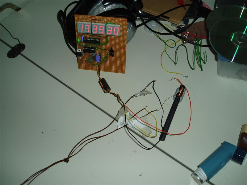
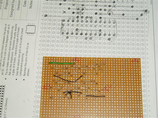
I’ve built a simple decoder circuit on some breadboard, using a PIC. The inputs to the decoder are +5v, 0v and the time code signal obtained from the receiver. The PIC has code running on it that decides whether each pulse is a 0 or a 1, it does this by using simple time delays and bit reads.

I started writing the PIC program in assembly language, but it became hideously complicated when trying to extract the time from the list of 1’s and 0’s, so I moved on to using a program called mikroBasic. This program allows me to write a PIC program in BASIC, which is then compiled into assembly language, which I feed to Winpic to program the PIC using the programmer I made.

The program I have made stores the current time in variables in the PIC’s memory. I then needed a way to somehow get the time out of some memory onto an LED display. I tried a few different chips for interfacing with an LED display, and finally settled on a Maxim MAX7219. This is a ‘Serially Interfaced, 8-Digit, LED Display Driver’, which essentially means that I connect this chip with up to 8 LED digits (I’ll only be using 6, hh:mm:ss) and then program the chip through a serial SPI BUS, telling it what numbers to display. There are three inputs on the MAX7219; CLK, SDA and CS’. These three inputs are connected to a PIC output port. I have then written code that accesses the SPI capability on the PIC, allowing us to send data to the MAX7219, telling it to display whatever digits we want.

I had originally stated that I was going to use a PIC 16LF84A, but I’ve now decided to use a PIC 16F88. This is because the 16LF84A doesn’t have a built in SPI capacility and the fact that the 16F88 has more memory and is cheaper.

The only problem I face now is finding an LED display to use! Farnell sell a perfect display (click), but you need to spend £20 before they ship anything to you, so that’s not really an option. I could use Maplin, but they only have red digits in stock (the green ones are in their catalogue but there is no stock in any store, work that one out), and I’d like the display to be green. Also, I’d like the seconds to be smaller than the hh:mm, and Maplin don’t have any small LED digits in stock, not very helpful at all really.

Looks like I have some hunting to do!

Note that I have decided to wait until I’ve finished this project before knocking up a circuit schematic or putting the code up, it doesn’t make sense to stick anything on the net until it’s final, as it changes so often.