Update

receiver success!

pc120042.JPGAfter going through the theory on the receiver circuit below, I’m pleased to report that I’ve had some success with a fairly simple little circuit that I knocked up.

After a lot of trial and error with capacitor values (which culminated in me asking the guy in Maplin for 2 of every value capacitor he had) I managed to hit upon the right combination of capacitance and inductance for me to receive a fairly good 60kHz signal, as the rather shaky mobile phone video below shows! The combination that worked for me was a 470pF in parallel with a 330pF capacitor, making a total capacitance of 800pF. The inductor (antenna) that I used was Maplin code LB12N, with all of the windings wired up in series. According to a datasheet Maplin provided for this antenna, this should equal an inductance of 3.5mH, but I’m not convinced. Hey ho – it receives the signal fine!

Click here to see a video of the receiver in action, showing the signal on my scope. The length of time that the carrier is sent (i.e. there is fairly big signal on the display) decides whether a 1 or a 0 is being sent. This results is a string of 1’s and 0’s, which can be decoded to give the current time and date.

I’ll knock up a quick diagram of the 60khz receiver circuit and post it here in the next few days, incase anyone’s interested!

Receiver Circuit

Been a little while since I’ve updated this, but I’ve been hunting down an oscilloscope to try and develop a receiver circuit, trying to work on the circuit at work (where I have access to every piece of test equipment under the sun) in my lunch breaks has proved difficult as I’m too busy at work to give it time!

I’m using a bog standard LC circuit (simply an inductor and capacitor in parallel) to pick up the 60kHz signal, by choosing certain values of inductor (L) and capacitor (C), the inductor can be made to resonate at a particular frequency, given by the equation below.  Basically, if you have the LC circuit resonate at 60kHz it’ll pass anything it receives on 60kHz into the next stage of the circuit.

  where f=frequency (hertz), L=inductance (henrys), C=capacitance(farads)
Only a very small signal is received (sometimes only a few millionths of a volt), so this needs to be amplified before anything can be done with the signal.  I will be using a JFET for an initial amplification, which will then be fed into an op-amp.  The reason for the JFET is that it has a very high input impedance (as good as an open circuit), so none of the signal will be lost to ground, which is very important when you’re talking about millionths of a volt.

Once the signal has been amplified, it can then be rectified (turned into a DC voltage level).  I’ll probably then use a comparator to make the signal a perfect digital signal, before feeding it into an input pin of a PIC.

Due to the nature of the circuit, I probably won’t be able to build it on a breadboard (prototype board, plug board whatever you want to call it!) before putting it onto stripboard, because breadboard is famous for being useless for RF applications because of stray capacitances and inductances through the board, which make any half sensitive circuit you put on it oscillate horribly.

My local Maplin seems to have sold out of everything I need to make a suitable inductor (antenna), so the building is delayed until they get their act together and order some bits in!

Meanwhile, I’ll plan and get the amplification stages of the circuit onto some stripboard and test basic amplification functionality.

PIC programmer works!! (eventually…)

PIC ProgrammerIt took a while to get working, but I’ve finally got the PIC programmer working perfectly with my PC!

I’ve included the final circuit below, I can confirm that this works 100%, with Winpic PIC programming software, using NOPPP.ini that is included with Winpic (don’t bother with the NOPPP software on the official site). You can write and read code from the PIC, it works a treat!

The reason it took a while to get working was the fact that one of the resistors in the NOPPP schematic was causing the logic levels on the input to the parallel port to be a little on the low side, meaning that the 1’s and 0’s weren’t being read into the parallel port correctly. The resistor in question is R6, which I’ve removed from the schematic linked to below. I’ve also added the 7805 voltage regulator that I talked about previously into the schematic.

PIC TestI constructed a simple test circuit on the corner of some stripboard and came up with some simple code to flash an LED to confirm that the PIC was being programmed correctly, it was! If you’re not sure how to write code for PICs, then I’d recommend the PIC Tutorial, this will show you how to construct a simple test circuit for your PIC, and give you all the information you need to know to start learning how to program your own PIC.

The final PIC Programmer circuit that I used and can confirm works perfectly is given below. It’s important to note that the power supply for the circuit must be at least 12.0v, if your power supply provides 11.9v then it’s likely that your PIC will be programmed, as the 12v is used as a signal for the PIC to initiate the programming sequence.

Revised, working NOPPP schematic:

NOPPP Schematic

Next on my to-do list is to come up with a simple receiver circuit to receive, amplify and demodulate the 60kHz time code signal that will eventually be fed into one of the PIC’s input ports. I suspect that this will take a while, based on the fact that my only (realistic) component supplier is Maplin Electronics. Maplin have become notably poor in recent years for supplying electronic components, discontinuing hundreds and hundreds of components in order to replace them with stuff you can buy from Argos, hey ho!

I’ll get to work on a 60kHz receiver circuit!

Designing a PIC Programmer

The first thing on my to do list is to make a PIC Programmer, so that I will eventually be able to get the code I develop for decoding the time signal from my PC onto a PIC.

One of the beauties of using a PIC in this project is that all of the time code decoding and drive for the LED display is handled by firmware that I write and program to the PIC. This means that if the time code format ever changes (VERY unlikely!) or I want to change how the display works or whatever, I can easily just tweak the firmware code and program it to the PIC. This is not possible with hardware, without physically replacing components.

Another good thing about using a PIC is that it reduces the component count enormously.

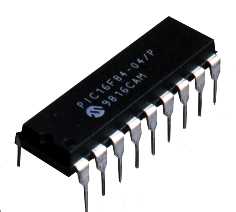
I’ve decided to use the PIC 16LF84A. This device has two ports, a 5-bit PORT A and an 8-bit PORT B. Each bit can be individually set as either input or output. I had originally intended to use a 16F84, but it turns out that these are now obsolete, but the 16LF84A is a pin for pin replacement that also uses the same programming interface as the 16F84. I’ve chosen the 16LF84A simply because it’s the only PIC device I have experience with!

As far as PIC programmers are concerned, the simplest programmer schematic I’ve found is the ironically titled No Parts PIC Programmer (NOPPP). This simple circuit uses a PC parallel port to program the 16F84. This type of circuit was what I had in mind for a programmer, finding a schematic for one that someone has tested is great! I’ve a fair amount of experience in using the parallel port to control external devices and I have to say that it’s a brilliant interface, so much easier than serial and USB communication. I’m sad to see parallel ports disappearing from PC motherboards, although I’m sure there are some USB > Parallel converters out there!

I could not find any veroboard layouts for the NOPPP, so I made my own layout, which will appear here soon!

To program a PIC you need two voltage levels, 12v and 5v. To get these levels I simply used a 7805 5v voltage regulator. The 7805 will convert 12v to 5v nice and simply, meaning that my circuit has just one voltage input, which is 12v. The circuit then uses the 12v in the parts of the circuit that need 12v, then feeds the 12v into the 7805, the 5v output of which is used in the parts of the circuit that need 5v. In order to make the stripboard layout nice and neat, I’m going to buy a PCB mounted 3.5mm mono socket, that you can connect 12v to. Easy peasy.