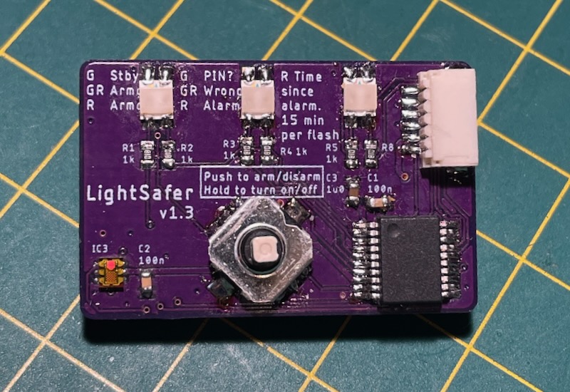
Updated with a new version - May 2025!
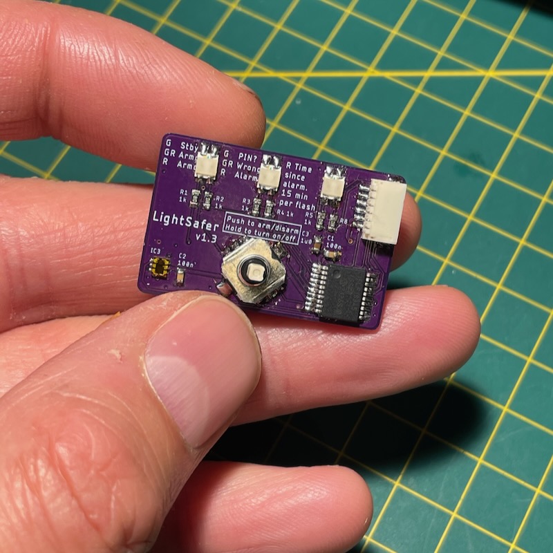
I wanted a simple device that would tell me if somebody had been in my hotel safe whilst I was out on holiday, so I designed LightSafer. LightSafer is a tiny 33 x 21 mm (1.3 x 0.8 inch) gadget with PIN code entry that lets you know if somebody has been snooping around in your hotel safe (or sock drawer).
It's completely silent. You just press the button to arm LightSafer, put it in your safe and if anybody opens the safe and fails to enter the correct PIN, the alarm LED lights. Once the alarm is triggered there is no way to turn it off. Even if the battery is removed, as soon as a new one is put in, the alarm LED lights straight back up.
A random pattern of LEDs is generated on first power-up and this is presented to the user when the device is successfully disarmed. This prevents an adversary reprogramming or replacing your device in the field - they won't know your unique LED pattern and so won't be able to replicate it. If you disarm Lightsafer and it doesn't present your unique pattern then you know your device has been reprogrammed or tampered with.
Entering the correct PIN is the only way to disable the alarm.

Already got LightSafer? Read the LightSafer User Guide for a full description on how to use it!

At the heart of the device is a PIC microcontroller, specifically the PIC16LF18345. The correct PIN is stored in the built-in EEPROM and the the code protect bits have been set. This prevents anybody from being able to dump the code of the PIC and read out the EEPROM.
The light sensor used is a TSL2591. I did originally use the APDS-9301, which supported 3 volt operation, but they were discontinued so I moved to the APDS-9300. This also went obsolete, so I've now moved to the TSL2591. This device appears to be popular in the hobbyist community so I hope it'll be supported for a long while yet. The sensor uses an I2C interface to the PIC and has a handy interrupt feature which can wake the PIC when a certain light level is reached.
LightSafer is powered by the ubiqitous CR2032 coin cell. The voltage of these coin cells can be anywhere from 3.3 volts to around 2.5 volts. The TSL2591 works down to 2.7 volts according to the datasheet, so I made sure to include a voltage indication method on power-up, so the user knows when the battery drops to below 2.7 volts. See the user guide for info. I've done this by wiring the battery through a potential divider into an ADC input on the PIC.
Low power consumption is really important - I wanted to leave the coin cell permanently in LightSafer, so the power consumption when off had to be tiny. The PIC has a very low power consumption mode, but the TSL2591 consumes 2.3μA when in sleep mode, a bit more than I'd like. To get round this, I decided to power the TSL from an IO pin on the PIC. That way, I can absolutely ensure that the power consumption of the TSL is 0 when I want it to be. There are some complications associated with doing this - you need to make sure that all the IO into the TSL is also at 0V when its power is removed, otherwise you'd back-feed the device, but I can manage that in software. The PIC sits in a super low power sleep mode, waiting for an interrupt from the button press to turn it on.
The interrupt feature of the TSL2591 also lets me save power. When LightSafer is armed inside the safe, the light sensor is configured by the PIC to raise an interrupt when the light exceeds a certain level. This lets the PIC go into a low power sleep whilst it waits for the light sensor to wake it up.
| State | Current Consumption @ 3.0V |
|---|---|
| Off | 0.13 μA 176 years from a CR2032! |
| Armed (i.e. sat in your safe) | 284 μA |
| Alarming | 1.2 mA |
User input is through a 5-way joystick: up, down, left, right, push. LightSafer uses an 8-digit PIN for disarming. Digits 1-4 can be used in the PIN - 1 is up, 2 is right, 3 is down and 4 is left. For example, a PIN of 14322312 would be up, left, down, right, right, left, up, right. The device is turned on and armed by pushing the joystick in. See the instruction guide below for more.
The design is fairly simple and comprises 6 LEDs (three dual colour packages), the PIC, the TSL2591 light sensor, a programming connector and some capacitors and resistors.
Warning: this isn't a very pretty schematic! Click it to enlarge.
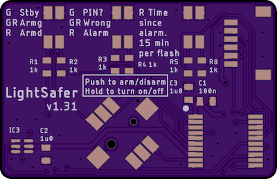
I wanted to try and get a description of what each of the LEDs meant onto the PCB, so the hardest part about the PCB design was trying to fit in the silkscreen! I've just about managed it though, you don't have to squint too much.
The PCB is shown below. As with all of my projects (see burningimage.net), I've used oshpark.com to manufacture the PCB. If you're interested in making your own LightSafer then you can even order yourself one by clicking the button below! They're only $5.45 for 3 boards, shipped worldwide for free.

The BoM for the project is given below - I've included links to component suppliers where available. Any manufacturer will do for the resistors and capacitors, but I've given links for the ones I bought anyway.
| Ref Des | Qty | Description | Package | Manu. Part Number | Mouser Part Number |
|---|---|---|---|---|---|
| BT1 | 1 | CR2032 battery holder | - | 3002 | 534-3002 |
| C1 | 1 | 100n capacitor | 0603 | 885012206071R | 710-885012206071R |
| C2-3 | 2 | 1u0 capacitor | 0603 | 885012106030 | 710-885012106030 |
|
IC1 |
1 | PIC microcontroller | SSOP | PIC16LF18345-I/SS | 579-PIC16LF18345I-SS |
|
IC3 |
1 | Light sensor | - | TSL25911FN | 985-TSL25911FN |
| SW1 | 1 | 5-way joystick | - | SKRHADE010 | 688-SKRHAD |
| R1-5, R8-10 | 8 | 1k resistor | 0603 | CRG0603F1K0 | 279-CRG0603F1K0 |
|
LED1-3 |
3 | Bi-colour surface mount LED | - | HSMF-C155 | 630-HSMF-C155 |
|
JP1 |
1 | 6 way JST programming socket | - | SM06B-SRSS-TB | 306-M06BSRSSTBLFSNPP |
The PIC code was written in C using MPLAB, using the free MPLAB XC8 compiler. The source code is given below. It includes the compiled hex file, so you can just program this directly into the PIC without compiling. The pins on the JST programming header map 1:1 to the PICkit 2/3/4 programmer header. Alternatively, you can send boards to me and I can program them for you.
Read the LightSafer User Guide for a full description on how to use LightSafer.
Andy C
May 2025
tribune.gadgets-9y@icloud.com